MIM design is similar to plastic molding design; this is due to the similarities in the molding process. Fortunately, the MIM process provides a level of design freedom that is unmatched by other metal manufacturing processes. MIM offers the ability to create overhangs, undercuts, threads, and other complex geometries. At APP, application engineers and Ph. D. Metallurgists are on standby to work with customers to take their part design and engineer a production capable MIM component.
Download the MIM Design Guide
When designing a MIM part, there are a few key design aspects that must be considered. The first is part geometry. Taking some time to consider how a part will be set during sintering is important. Try to avoid geometries that overhang if possible; as these create difficulties when setting parts. Consider designing a part with a flat area to set the part on to decrease the cost of setting materials.

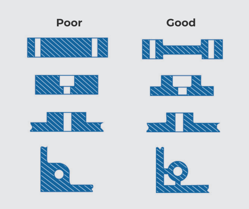
Where possible, maintain a uniform wall thickness. Uniform wall thickness helps with filling the part, helps to prevent sinks, and prevents warpage during sintering.

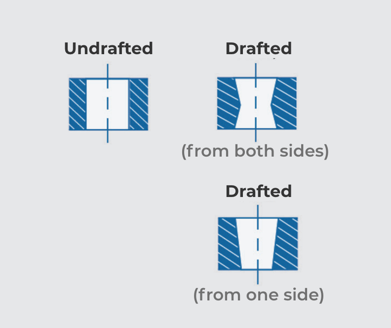
Add draft to cores or external undercuts to ensure easy release of the part from the tool.

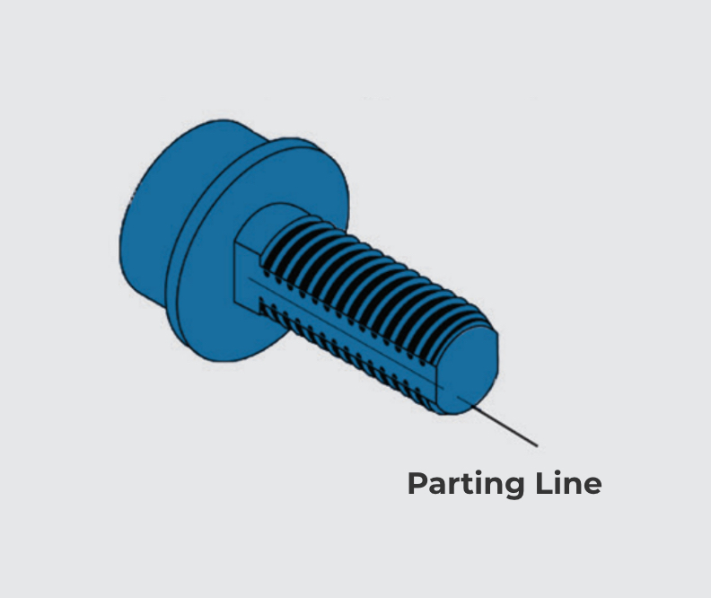
The MIM process also allows threads to be made during the molding process. When designing external threads flats must be included simplify the parting line.
A major factor to consider when designing a part for manufacture with MIM is tooling design. MIM tooling requires very specific design features; these include parting lines, gates, ejector pin marks, and cam actions.
Parting Lines: Every MIM part will have a witness line from where the two halves of the mold come together to form the cavity. However, creative design can help to hide the parting line. Stepping the parting line down the edge of a feature will make the parting line less apparent.
Gating: The gate is where the MIM feedstock is injected into the cavity. There are four most common gate types: tab, tunnel, jump and drop. Each gate type leaves a small vestige, so placement is complicated. You also want to gate into an area of the part with the largest cross section, so you fill the part from thick to thin. On cylindrical parts, filling as close to the center axis as possible will help prevent sintering distortion.
Ejector Pins: Ejector pins serve to remove the part from the tool cavity. However, ejector pins leave witness marks on the part. Consider designing the part in a way to place these marks in an area that is unseen on the part when it is assembled.
Cam Actions: Cam actions allow undercuts to be formed in the part, without the need for secondary operations. When designing a part with undercuts, keep in mind what direction a cam will have to move in to form the undercut. Design becomes more complicated when multiple cam actions are needed, because each one takes up a lot of space within the tool itself.
“Our customers rely on our expertise to design and develop robust MIM tooling to ensure the long-term success of their MIM parts.”
Metal injection molding, like plastic injection molding, can create near net shaped parts at high production volumes. These parts can have undercuts, recessed features, threads, bosses, and holes. The standard MIM part will tend to fit in the palm of your hand; however, APP has parts ranging from .05 grams all the way up to 100 grams.
The MIM process creates parts with near-wrought properties. MIM can achieve a part density of 94-97%. This is a key benefit over pressed metal parts. MIM parts also exhibit mechanical properties that are on par-with wrought or forged parts.
| Attribute | Minimum | Typical | Maximum |
|---|---|---|---|
| Component Mass (g) | 0.030 | 10-15 | 300 |
| Dimension (mm) | 2.0 (0.08 in) | 25 (1 in) | 150 (6 in) |
| Wall Thickness (mm) | 0.025 (0.001 in)* | 5 (0.2 in) | 15 (0.6 in) |
| Tolerance (%) | 0.2% | 0.5% | 1% |
| Density | 93% | 98% | 100% |
| Production Quantity | 1000 | 100,000 | 100,000,000 |
| *Features this small could have distortion | |||